Author Topic: Primary sprocket / clutch alignment/ modification guide  (Read 7796 times)

Online chaterlea25

  • Wise & Enlightened
  • *
  • Join Date: Jun 2009
  • Posts: 4015
  • Karma: 54
Hi All,
Here is my attempt to put together a guide to primary chain alignment issues that arise when fitting a 4 spring clutch to BSA A7/10 swing arm models and also issues arising when building up with parts of unknown origin
(Some information will refer to B series models)
There are three main considerations to address,
1)   primary chain alignment
2)   sliding plate to shaft adaptor fit and clearance
3)   primary case / primary chain clearance problems.

It would seem that some replacement clutches/adaptors sit farther out than others!!!
The shaft adaptors can vary in the depth that the internal taper is machined to.
This affects where the clutch chain wheel will sit in relation to the engine sprocket. It will also affect the depth where the scrolled portion fits into the sliding plate
Sometimes a bought in clutch will fit and line up “just so” more often than not it will not!!!
Clutches for single cylinder models need to sit farther onto the gearbox mainshaft than twins
The single cylinder models inner primary case position allows for this.

I will leave it to owners to decide which way they decide to adjust the alignment
If alternative shaft adaptors can be obtained or change the engine sprocket position?

I have measured up some components that I have to hand to provide some figures for comparison to reader’s machines
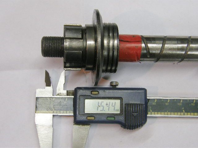
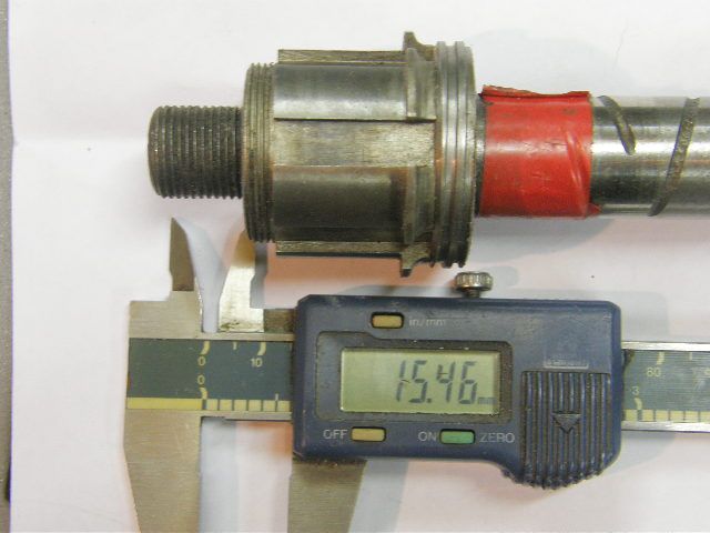
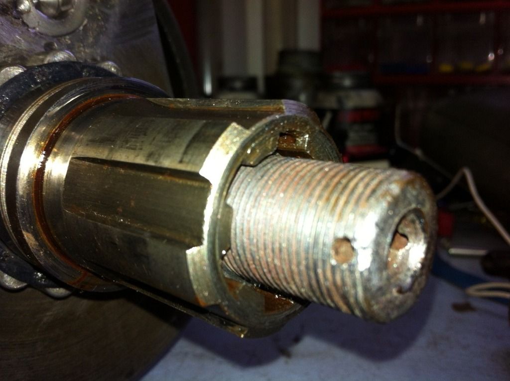
Firstly I measured how far a couple of gearbox mainshaft protrudes through the adaptor.
The original adaptor fitted on varying amounts on three different original mainshaft’s which leads me to the conclusion that the shaft tapers differ as well!!! Unless the shafts vary somewhat in overall length??

“Original” A10 adaptor,  showed 14.3 – 16mm, thread  protruding  depending on which main shaft it was fitted to, almost the same as a 6 spring adaptor


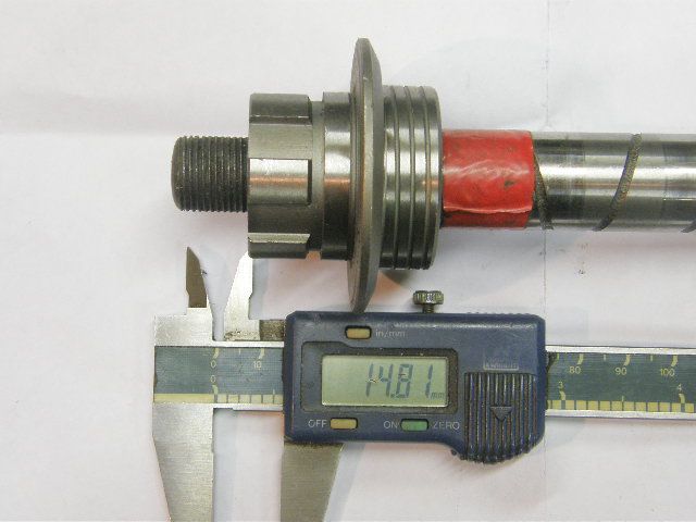
A pattern adaptor went on about 0.6mm less than original A10. (This is one of the adaptors where the scroll is cut in the wrong direction that were on the market )


Pearson Gold Star adaptor + 2.5mm more than original A10 (no photo of this)

Before checking the primary drive alignment make sure all the engine and gearbox to frame mounting bolts are fully tightened.
It is also worthwhile to check that the primary chaincase mounting face on the crankcase is parallel to the gearbox mounting bottom plate, a straight edge and steel ruler will be good enough for this , If out of line loosen the engine / frame bolts a little and lever the engine in the required direction ..
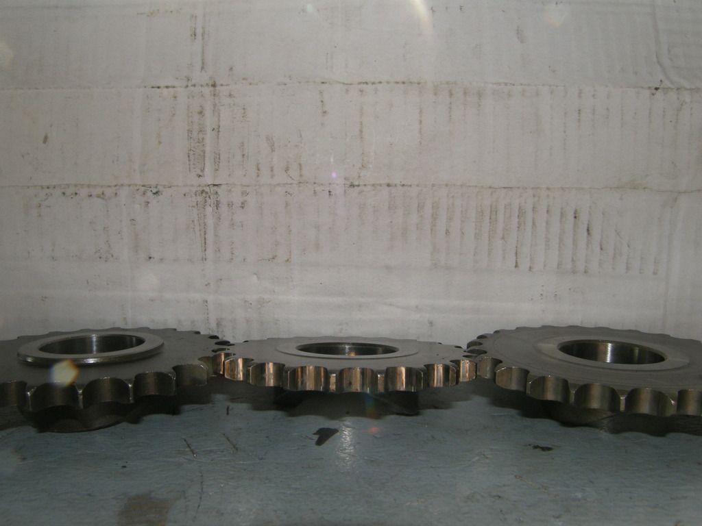
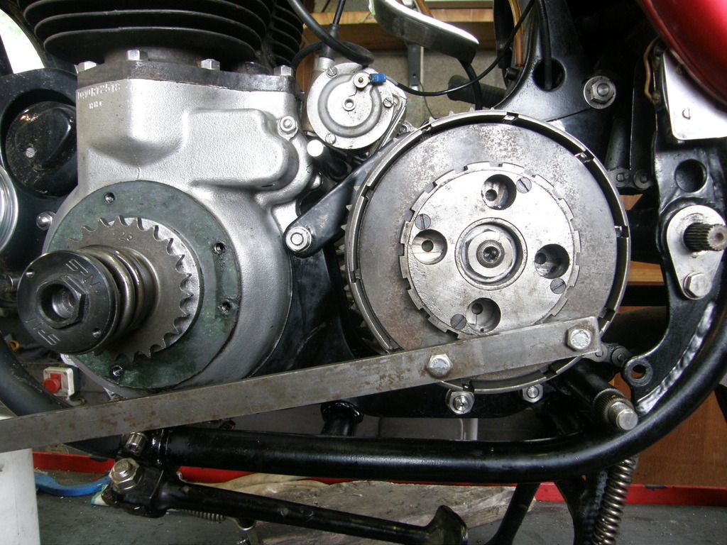
Trial fit the adaptor and chain wheel etc onto the gearbox shaft and use a straight edge to check the sprocket alignment
It’s a lot easier to use a straight edge on the rear face of the sprockets with the inner primary case removed


The other factors that can vary are the engine sprockets and crankshaft cushdrive sleeve shoulder width
For A10 models I believe the shoulder on the cushdrive sleeve should measure0.312in.
I have a range of engine sprockets, which vary from flat on the rear face to one with a shoulder of 0.100in.


If required shims can be added between the crank spacer and cushdrive sleeve if the engine sprocket needs moving outwards a little.
Large adjustments here will compromise fitting the cushdrive nut!!
I would advise against fitting any shims between the sprocket and cushdrive sleeve shoulder as these parts move relative to each other
The cushdrive sleeve must extend past the end of the crankshaft spline so as the nut can clamp the assembly solid through the main bearing to the crankshaft face.
The crankshaft cush drive nut should be tightened to 65ft-lbs, I use some Loctite threadloc on the threads rather than the lockwasher


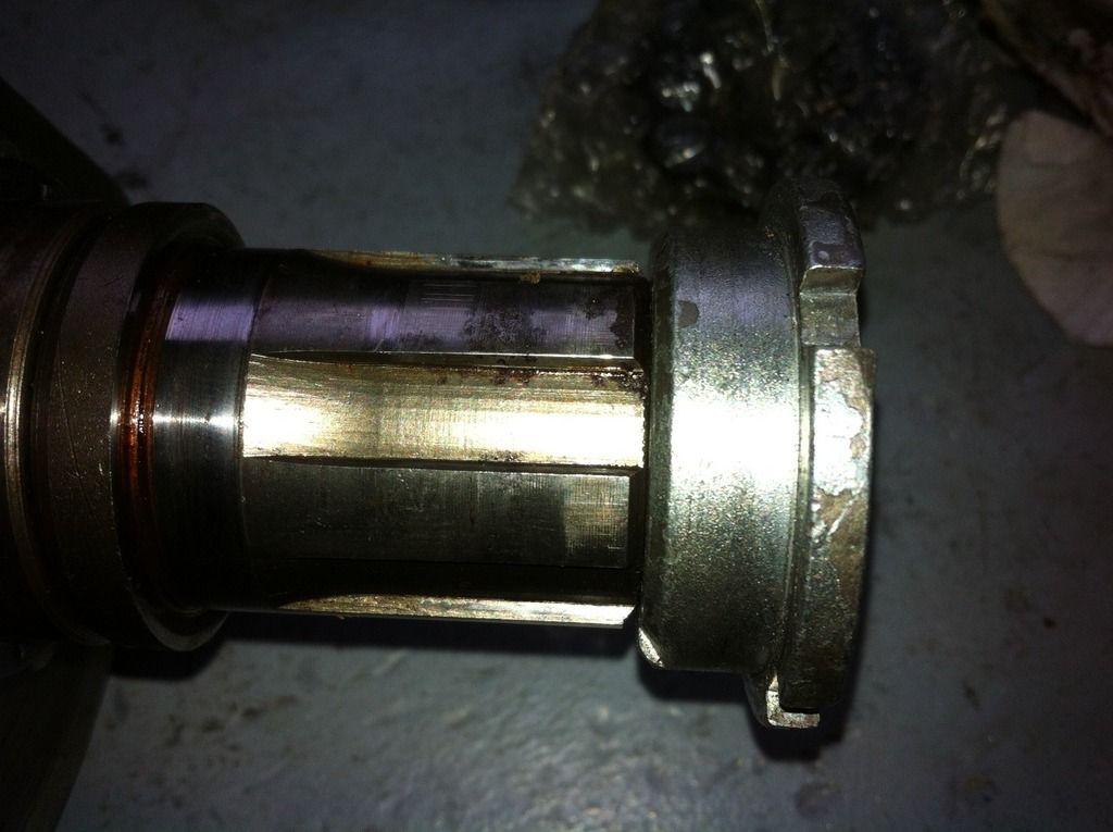
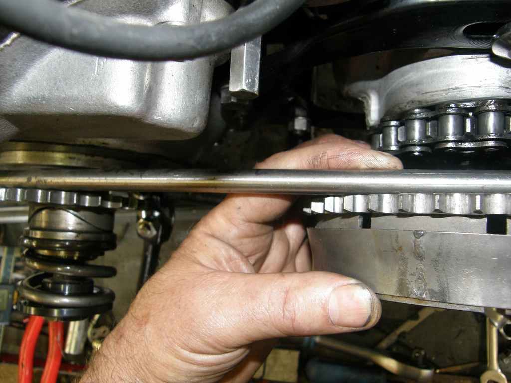
The photo above shows the limit of the cush drive movement, (no spring fitted for clarity)

The primary chain needs to be a very good quality  “standard” chain
“H” (heavy duty) chains are wider and can rub on the chaincases

It may be necessary to adjust the inner primary case position,
Check if spacers/washers have been fitted on the lower rear inner case to frame mount
Remove this mounting bolt and any spacers temporarily,
Fit some temporary 5/16whit bolts in place of the front primary to crankcase screws
This will keep the inner case square and in its proper position, the same as when the outer has been fitted
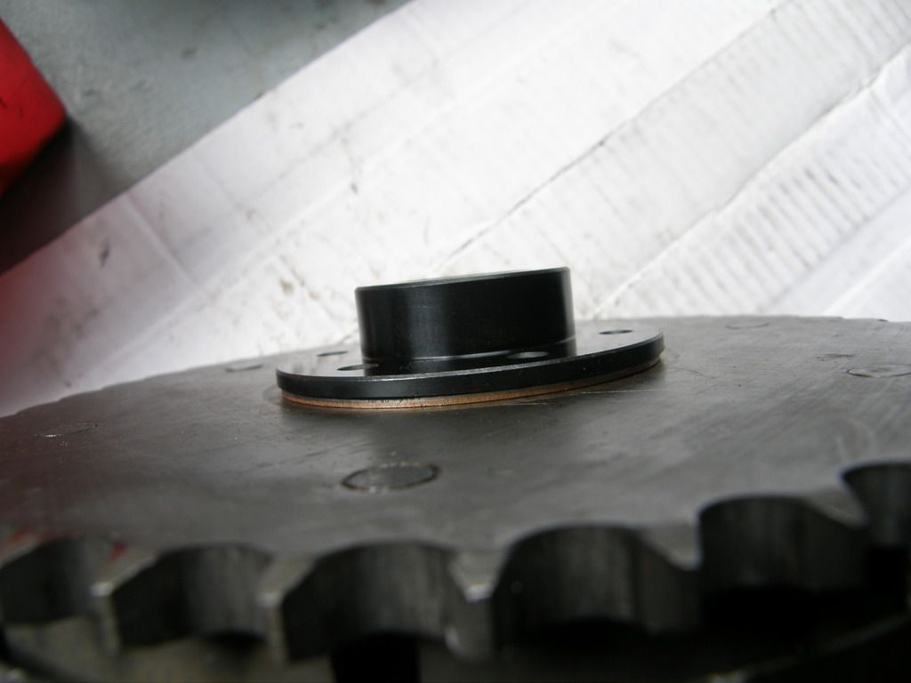
Trial fit the shaft adaptor of the new clutch on the mainshaft to see where it sits in relation to the sliding plate and the amount the mainshaft protrudes through it
If the adaptor sits well into the sliding plate, without being tight against it then all is well in that regards,
If the inner case position needs adjusting to clear the chain or shaft adaptor, gaskets can be added or removed between the crankcase and inner primary case,
Once the inner primary case position is finalised add spacers or washers as needed to the lower rear inner case mounting bolt, do not strain the inner case.


The pattern sliding plates available are to my mind poor quality; the hole for the scroll is usually non-circular and or oversize,
The originals were definitely better but still quite a loose fit on the scroll
I have resorted to a couple of different methods to improve the sealing,
including a machined close fit bush silver soldered to the plate,
or a machined up steel ring that holds an X ring seal
Recently I read that oil can leak between the plate and the riveted in centre piece,
Yes it can!! Some sealant pushed into the v gap may help
The “Pearson “ or similar sliding plate with a proper seal and bush are probably the best remedy???


I found when I first built my SR that with the original shaft adaptor fitted, that a flat inner faced crank sprocket lined up with the clutch, however in this instance it caused another problem with the sliding plate being tight against the adaptor and lack of chain clearance!!
I fitted a thinner spacer between the crankcase and inner primary to overcome this issue


Some years later I wanted to increase the overall gearing and also to try and improve the clutch,
I fitted an adaptor bought from SRM which has a thrust washer arrangement like the A65 models, 


This adaptor does not have a scroll machined into it, a felt washer is fitted between the adaptor and sliding plate to act as a seal
At the same time I fitted a new crankshaft sprocket, supplied by SRM but Wassel brand. This sprocket has a shoulder on the rear face (I forgot to measure it??)

Either by chance or good measure the primary sprocket alignment turned out perfect!!
I then had to refit the original steel spacer between the crankcase and inner primary

To take advantage of the thrust washer set up on the SRM adaptor a clutch friction plate is fitted at the rear of the clutch basket, to get this to fit I had to file the slots in the basket deeper so as the plate would sit against the inner face


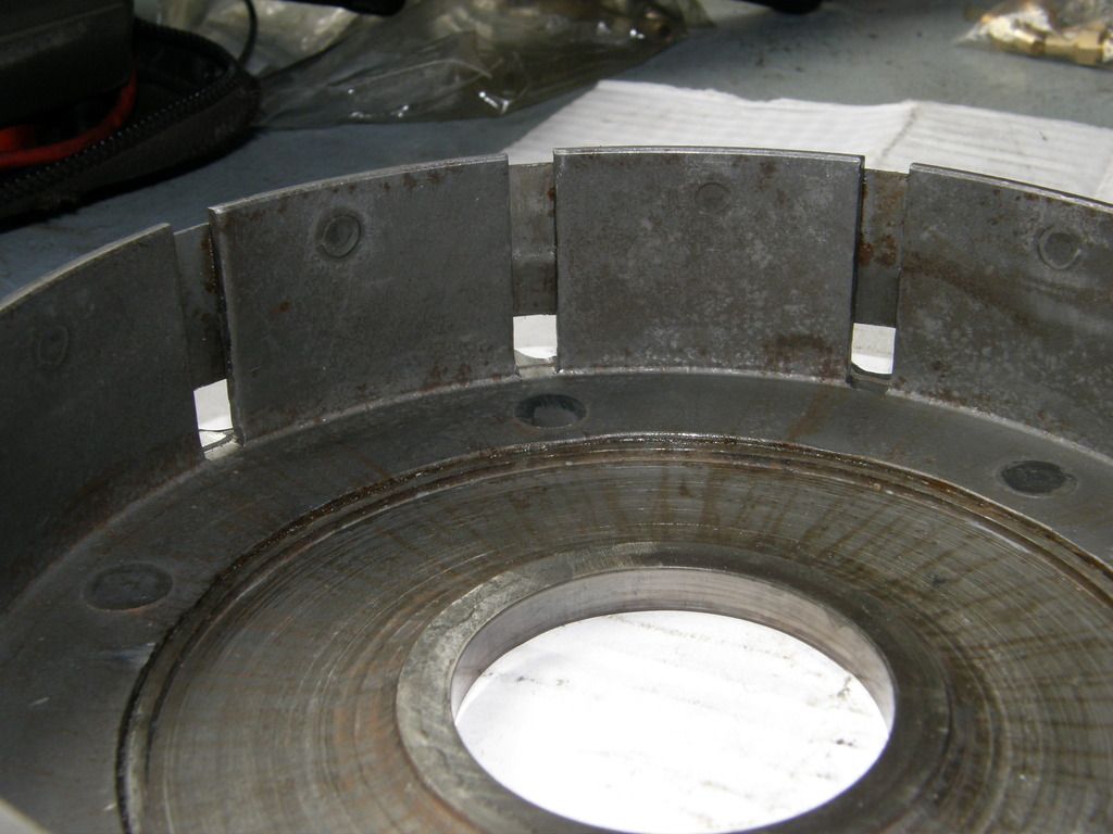
The inner clutch drum will need the lip at the inside removing or what I did was to machine out the centre hole in the rear friction plate to fit over the lip
An extra plain clutch plate was needed in my case to make up the plate pack thickness


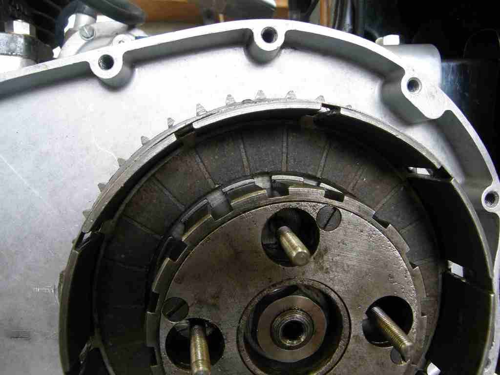
A homemade clutch locking tool made from some old plates bolted together and to a length of steel can easily be made ,
I use some Loctite threadloc on the centre nut threads and tighten to 65ft-lbs


HTH
John

adm edit: safety copy of all imges (in case external hosting changes, with loss os pictures in post)

www.a7a10.net/forum/extimagebackup/basket_slots_deepened_zpsismujlru.jpg
www.a7a10.net/forum/extimagebackup/6_spring_adaptor_zps6aiizom8.jpg
www.a7a10.net/forum/extimagebackup/clutch_tool_zpsq6hwivb8.jpg
www.a7a10.net/forum/extimagebackup/crank_sleeve_zpsprmyrblq.jpg
www.a7a10.net/forum/extimagebackup/nut_fitted_zpsylysirs0.jpg
www.a7a10.net/forum/extimagebackup/limit_of_travel_zps3brxtuth.jpg
www.a7a10.net/forum/extimagebackup/modded_plate_zpsizsdddv2.jpg
www.a7a10.net/forum/extimagebackup/original_adaptor_fit_zpsb352oo1t.jpg
www.a7a10.net/forum/extimagebackup/pattern_adaptor_zpsaeph5eqy.jpg
www.a7a10.net/forum/extimagebackup/straight_edge_zpscof4zluh.jpg
www.a7a10.net/forum/extimagebackup/SRM_adaptor_zpsund7ukk1.jpg
1961 Super Rocket
1963 RGS (ongoing)

Online muskrat

  • Global Moderator
  • Wise & Enlightened
  • **
  • Join Date: Jul 2009
  • Posts: 10760
  • Karma: 130
  • Lithgow NSW Oz
    • Shoalhaven Classic Motorcycle Club Inc
Thanks for taking the time to do that John. Hopefully that will save a few headaches.
 *thanks* *good3* *clap*
'51 A7 plunger, '57 A7SS racer now a A10CR, '78 XT500, '83 CB1100F, 88 HD FXST, 2000 CBR929RR ex Honda Australia Superbike .
Australia
Muskys Plunger A7

Offline oldbeezageezer

  • Moving Up
  • **
  • Join Date: Mar 2015
  • Posts: 40
  • Karma: 0
Great pics John.
Just fitted new clutch to my A10 S/A and now looking at the cush drive. Mine has the standard retaining nut but p/o has added an additional nut to he shaft. I have just got that off and found there was no split pin. Hence the extra nut. I also noticed that the retaining nut does not use all the threads on the shock absorber shaft. Should the nut tighten up against the end of the splines on the sleeve?

Would I be better off getting the SRM retaining nut that you have used and doing away with the split pin?

Thanks
Alan
1954 A10
1972 CB 350 K4
YAMAHA XV750
1999 CBR600

Online chaterlea25

  • Wise & Enlightened
  • *
  • Join Date: Jun 2009
  • Posts: 4015
  • Karma: 54
HI Alan,
Quote
Should the nut tighten up against the end of the splines on the sleeve?
YES!!
Refer to the photos above (no 7) which shows the nut butting against the sleeve
The nut needs to be torqued as mentioned to 65ft lbs
This is one of the most abused and misunderstood items on pre unit BSA's *sad2*

If the nut has not been fully tightened then I would check the sump plate for broken shims *sad2*
Read up the current thread on crank end float http://www.a7a10.net/forum/index.php?topic=7303.0

If you can make up a tool to tighten the existing nut then they are ok, A big socket can be cut to leave 4 dogs to engage in the nut, the SRM nut just makes the job easy, It will also accept one of their timing discs

Which ever nut you use, degrease the threads and use thread locking fluid, do the same with the clutch centre nut, 65ft /lbs also

HTH
John
1961 Super Rocket
1963 RGS (ongoing)

Online chaterlea25

  • Wise & Enlightened
  • *
  • Join Date: Jun 2009
  • Posts: 4015
  • Karma: 54
Hi All,
Following Orabanda and Richards requests, I went and took some photos and measurments of some cush drive components from a single cylinder swing arm 1955 B33 and a 1960 A10, plus some other relavent pieces
Recently I bought a new cush drive spring to suit a late Gold star, this is longer and has 3 3/4 turns where as the A10 springs have 3 1/4 turns ?? The B33 spring (broken!!) also had 3 1/4 turns ????
I found that the depth of 3 cush drive collar shoulders varied from 9.2mm , 9.5mm & 10mm   ?????
The shoulders on the cush drive nuts varied a pattern one at, 11.2mm, SRM nut at 12.7 and the one from the B33 at 14.5mm
I added the photos here in an effort to keep the information in one place

HTH
John
1961 Super Rocket
1963 RGS (ongoing)

Online chaterlea25

  • Wise & Enlightened
  • *
  • Join Date: Jun 2009
  • Posts: 4015
  • Karma: 54
Hi
More photos of the 1960 A10 bits

John
1961 Super Rocket
1963 RGS (ongoing)

Offline duTch

  • Ricketty Rocketty Golden Flashback
  • Wise & Enlightened
  • *
  • Join Date: Oct 2011
  • Posts: 4528
  • Karma: 41
 That's good John, assuming it's (spring) 8mm wire, that'd make the ID ~42.8 which is much more ideal than the one I bought.

 Where'd you buy that/ how much..??

 cheers *beer*

 Edit, Nov 1 '15; details provided in "Re: A10 Crankshaft Cush Drive; Clarification sought" thread
Started building in about 1977/8 a on average '52 A10 -built from bits 'n pieces never resto intended -maybe 'personalised'
Have a '74 850T Moto Guzzi since '92-best thing I ever bought doesn't need a kickstart 'cos it bump starts sooooooooo(mostly) easy
Australia

Online orabanda

  • Wise & Enlightened
  • *
  • Join Date: Nov 2008
  • Posts: 1180
  • Karma: 24
John,
You are a wealth of knowledge; thanks for going to all this trouble - very helpful!

Richard

Online Sav

  • Valued Contributor
  • ****
  • Join Date: Jul 2011
  • Posts: 298
  • Karma: 6
  • VMCC Men of Kent and BSAOC member
    • TT Website and Forum
Just had this one myself, took the primary chain case off my 1961 A10SR to service and clean the clutch which has been dragging/slipping a little, only to find the cush drive jammed open with the tips of the lobes just engaged, more travel than the limit on the example here, just not quite enough to drop over to the next lobe but to get wedged at the top of the travel. The nut had not loosened off either and split pin was in place. SRM nut arrives this morning so should know more then.

Appreciate finding threads like this.

SRM say the cush drive should not be able to flip over to the next lobe and recommend not using the split pin with their nut, just 65 lbs ft and lock tight.
1961 A10SR, spent a fortune at SRM
1961 A7SS, finally the right green
2011 1937 Empire Star, twin port, high pipes, 2023 off to pastures new.
2022 Gone to the dark side and bought a 1981 Honda Benly, electric leg for my old age! done 450 miles!
2023. 1972 Honda CL350 added. Another electric leg bike with a bit more oomf
White Cliffs Country

Online chaterlea25

  • Wise & Enlightened
  • *
  • Join Date: Jun 2009
  • Posts: 4015
  • Karma: 54
Hi Sav,
If the lobes can ride up and lock with the nut tight then its either worn lobes or mismatched parts fitted
If the inner sleeve is the wrong one same applies

John
1961 Super Rocket
1963 RGS (ongoing)

Online Sav

  • Valued Contributor
  • ****
  • Join Date: Jul 2011
  • Posts: 298
  • Karma: 6
  • VMCC Men of Kent and BSAOC member
    • TT Website and Forum
Thanks John,

SRM nut arrived and it's a couple of mm lower profile than the one on there, so slightly more spring compression. That may be the answer, only time will tell.

Bike was an SRM complete engine timing side mod and rebuild a few years ago, so would hope that the parts were correct but something was not.

SRM nut had a horribly tight thread and I had to work it on/off turn at a time with everything wedged to get it free enough to use. On there now at a good 65 lbs ft in case of distorted reading and trusty locktight
1961 A10SR, spent a fortune at SRM
1961 A7SS, finally the right green
2011 1937 Empire Star, twin port, high pipes, 2023 off to pastures new.
2022 Gone to the dark side and bought a 1981 Honda Benly, electric leg for my old age! done 450 miles!
2023. 1972 Honda CL350 added. Another electric leg bike with a bit more oomf
White Cliffs Country

Offline kiwipom

  • Resident Legend
  • *****
  • Join Date: Jan 2011
  • Posts: 745
  • Karma: 8
hi guys, Sav says(SRM nut had a horribly tight thread and I had to work it on/off turn at a time with everything wedged to get it free enough to use. On there now at a good 65 lbs ft in case of distorted reading and trusty lock tight)
..i have in the past had probs like this and fixed them with (wait for the cry's of wwhhaatt) a slight smear of fine grinding paste then cleaned up after to remove any left on thread, worked for me, cheers
A10.G.Flash(cafe racer)Honda 250 vtr. Yamaha Virago XV920.

War! what is it good for?Absolutely nothing, Edwin Star.
NewZealand

Online Colsbeeza

  • Resident Legend
  • *****
  • Join Date: Aug 2015
  • Posts: 685
  • Karma: 4
Regarding Cush Sleeve Bearing Flange thickness, I thought this topic may be the best place to put it rather than starting yet another new topic. John's article is too good to not raise it again..
I read about Mosin's alignment issue whilst tackling my own.
See Topic "Touchy Feely"     https://www.a7a10.net/forum/index.php?topic=2689.45
There were strong opinions expressed that there may have been two flange thicknesses made by BSA, 5mm and 8mm. And perhaps the thicker flange is for the conversion to the 4-spring clutch.
There are two NOS Sleeve Bearings currently for sale from Thailand. Doesn't appear to be any wear, so maybe NOS. Whether it is genuine or not, the photos are interesting.

https://www.ebay.com/itm/Nos-BSA-A7-A10-Cush-Drive-Sleeve-42-0069-year-1956-62-/202824615614

Price is a bit too steep for me, but interesting dimensions. I printed one of the photos and scaled the flange to measure 4.45mm thickness. I know there are uncertainties in measuring off photos, but this flange is clearly closer to 5mm than 8mm. I had to machine 3mm off my own 8mm flange to get alignment.
Certainly adds weight to the "Two Flange Thickness" camp.
Col
1961 Golden Flash
Australia

Online JulianS

  • 1962 A10
  • Wise & Enlightened
  • *
  • Join Date: Mar 2017
  • Posts: 1385
  • Karma: 29
The whole primary drive was moved out by about 1/8 inch for the 1956 on twins and B31/33, at the same time the steel plate was introduced between the chaincase and crankcase, the reason being to allow space between rear of primary case and gearbox when fully enclosed rear chaincase was fitted.

You cannot mix  the 1954/55 twin and B31/33 primary drive parts with the 1956 on parts and keep it aligned.

Briefly mentioned difference in clutch sleeve in this Hap Alzina parts bulletin. It does not mention the engine sprocket assembly, though the part numbers are different, the bearing sleeve for 1954/55 part 67 1097 and for 1956 on 42 0069.


Online Colsbeeza

  • Resident Legend
  • *****
  • Join Date: Aug 2015
  • Posts: 685
  • Karma: 4
Hi Julian,
I don't think that moving the primary drive 1/8" explains the flange thickness variation after 1955.
I suppose I am drawing to attention that the Part 42-69 is being specified / sold at 5mm and 8mm. Both Draganfly (apparently) and the Thai seller indicate 5mm and I have seen it elsewhere as well. Most others agree on 8mm. I had to reduce mine from 8mm to 5mm which solved my problem, but I had assumed that the clutch centre I purchased from a Swap (autojumble) meet about 25 years ago was from a dubious source. Seeing a few advertised whose images indicate 5mm raised my curiosity.
Draganfly drawings show that for the "2 lobe All Models 1955-63 Except when alternator fitted", there are 3 Part Numbers:-
42-69 for 56-62 Model A, 65-2539 for 54-63 B & M Models, and 67-1134 for 1955 A Models.
Presumably, if 42-69 came in only 8mm flange thickness, then those with 5mm which otherwise look the same are from one of those other models or Gold Star.?  *rant*.
Anyway, I think this issue is irritating. *pull hair out* There doesn't seem to be any definitive answer so I'll leave it alone.
BTW Julian Thanks for your generous posting of many BSA and Hap Alzina etc documents over the years. They have been great and useful and a mystery how you could accumulate so many in one lifetime. *thanks*
Cheers Col
 
1961 Golden Flash
Australia